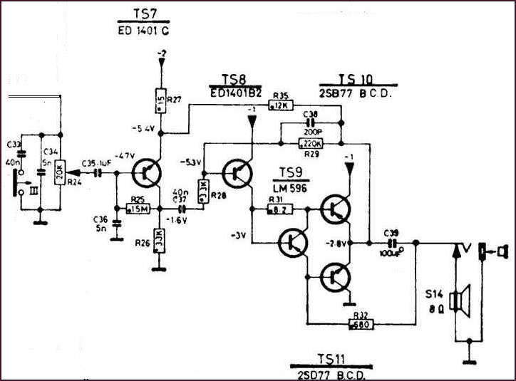
I have got a radio - Philips 90RL114/01. The RF part worked properly. The AF part
didn't work at all. I have measured the diode junctions of the transistors.
The last four directly coupled transistors were burned out and I was also not sure,
if there somebody has not tried to change the original transistors.
In the first stage of my version of the radio there was a rare transistor ED207.
This stage was not directly coupled and worked properly.
Mr.Eric Cassagne was so kind and sent me the circuit diagram of
his radio. (Merci beaucoup, Eric).
I have used only the audio frequency part of the circuit diagram for modelling it in LTspice.

For this part of the schema I have used the standard NPN and PNP transistors with small changes to get better results in LTspice analysis.
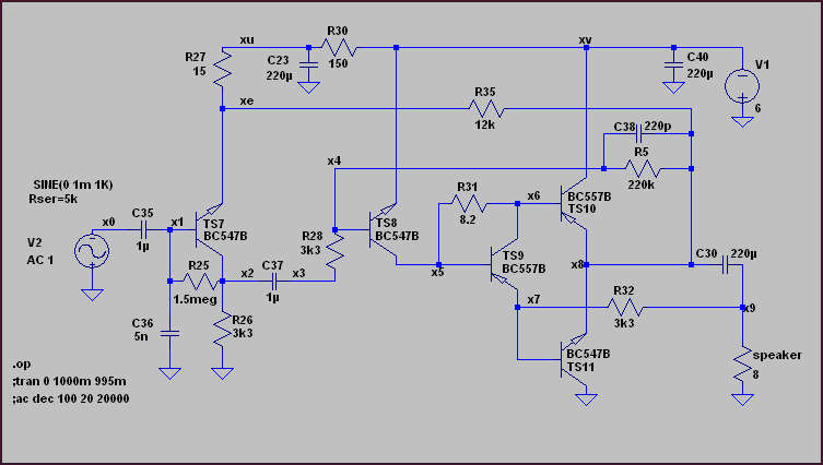
Transient - from 1mV p-p to 300mV p-p we see a small, but acceptable transient distortion from the last stage.

AC analysis -3dB: 10Hz to cca 10kHz.

But I have seen, that the version of my radio was apparently different.
In this step I have applied a camera and layers capability of freeware PaintNET.
So I could see both sites of the PCB on the same place varying the transparence of either of these two layers
using the opacity in the layers property window right down in the pictures.
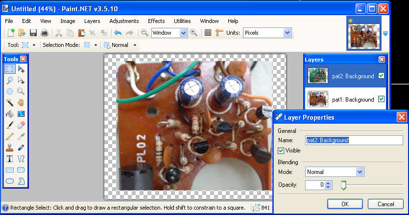
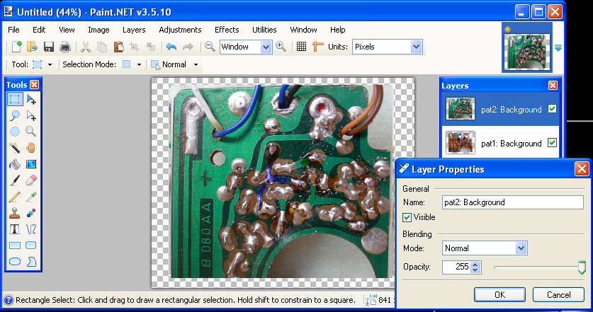
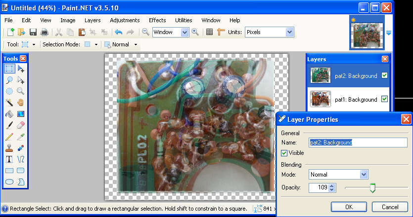
So after replacing the defect transistors with standard ones I could draw the circuit diagram of the AF part of my radio, which was, as I already mentioned different as the schema sent to me by Eric.
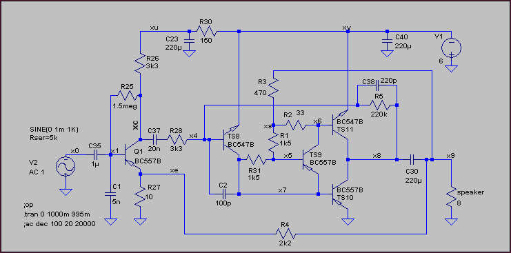
This schema hasn't brought satisfactory results in LTspice analysis. Under real conditions it worked with R2 value 15k instead of 33 ohm. But the symmetry and idle current consumption (50mA) were not nice and I didn't find a better solution only by changing the values of the resistors. The radio works, but I am not lucky with it. It could be very interesting to get the circuit diagram of the version of my radio. Maybe I can in the future find the reason of the bad results, if I'l get the factory circuit diagram.