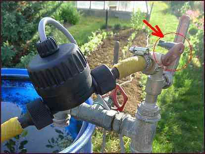
I have a garden with a well. This year we have not so much water as in the previous years. I have tested, that only 30-90 seconds the pump may work not to pump air into system and then 15 till 30 minutes wait, till the water level is again reached. Therefore I have bought a solenoid water valve. In idle state it is closed, in open state it takes about 1.5 ampere current from the 9V power supply.
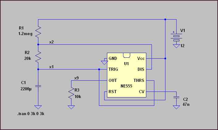
For this task I have used the old-well known NE555 wired as an astabile multivibrator.
How it works:
- The C1 capacitor is loaded through R1+R2 till threshold voltage THRS 8V(2/3 V1).
- After achieving the THRS voltage the DIS output opens and causes discharging of C1 through R2.
- Discharging is stopped at triger voltage 4V(1/3 V1), where again begins the loading phase.
Below is the wiring scheme of the control unit.
The voltage on the output V(x9) and on the C1 load / unload capacitor V(x1):
Important note: If you want to measure the voltage on C1 you need a device with big resistance on input.

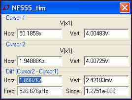
Time differencies between cursor 1 and cursor 2 slow loading (~1900s = ~30 min) and fast unloading (~30s):
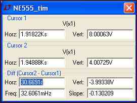
Instead of resistor R1 there was used a trimer 1M5 and instead of resistor R2 was applied a potentiometer 47k.
Now we have a suitable control unit. For opening the valve some parts more are needed:
Maximal current of output pin 3 of NE555 is 200 mA.
I have used a relay with can switch 230V/10A current to switch the 9V/1.5A current into the solenoid valve.
The current needed for switching the relay was about 30 mA at 12V. Don't forget a protective diode paralel
to relay winding, I have used a general purpose diode 1N4148.
For switching the valve instead of a relay also a power transistor could be used.
I have used 2 power supplies: 12V 100mA for the control unit with NE555 and a 9V 3A power supply for switching the valve electromagnet.
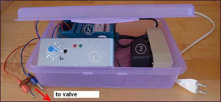
How it seems at the end:
1: control unit
2: power for the control unit (12V/100mA)
3: power for the solenoid valve (9V/3A) - used the body of an old accu loading unit.
Solenoid water valve:
