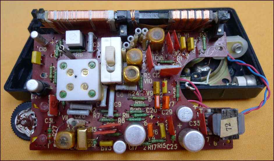
I got a radio Signal 304 from the former USSR. It is an MW/LW radio and all transistors are Si npn KT315B or pnp KT361B. Somebody has tried to repare it and the transistor V9 in the AF(audio frequency) amplifier was missing. I have replaced it with the same type, but it didn't work either.

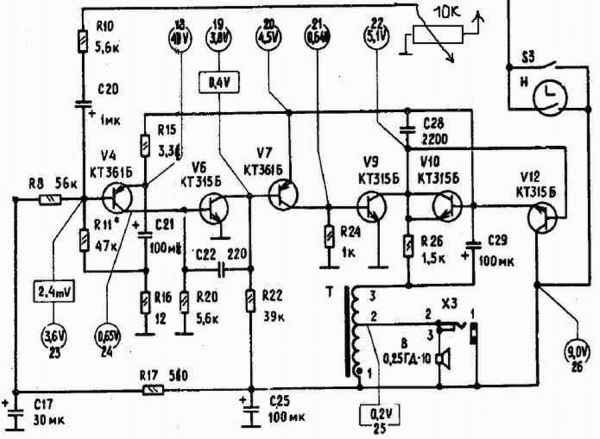
Therefore I have found the schematic diagram of Signal 403, which seemed to fit. And I started to study the wiring scheme. The HF part worked properly. At the end I have found the erroneous component. It was the transistor V6, both pn junctions of it were burned out. But before it I at first decided to examine the wiring scheme of the audio amplifier using LTspice. Interesting is the directly coupled audio frequency amplifier part of the schematic diagram:

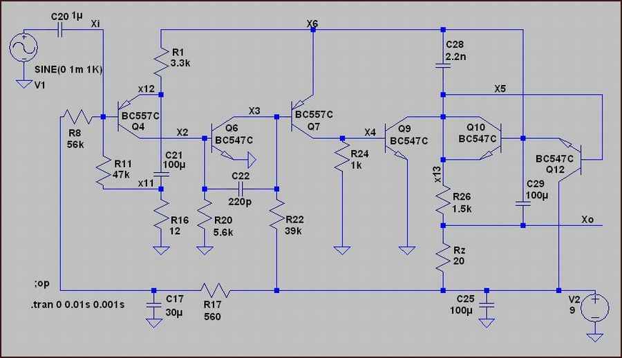
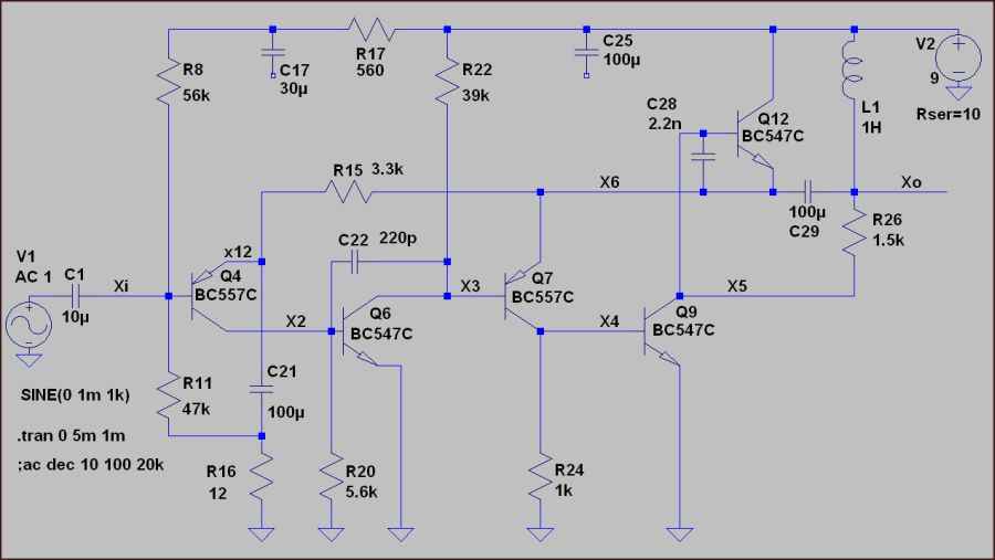
LT Spice schematic: (transistors are named Q4-Q10 instead of V4-V10.)
Instead of KT315B I have used another general purpose Si-npn transistor BC547C and instead of KT361B the BC557C.

For a better readability I have made another - equivalent scheme, the transistor Q10 is connected as a diode and this diode plays role in case of larger signals. For simplicity I have omited it in LTspice simulation schema. Thank Marcel van de G. for his notice.

Transient:
The voltage amplifying is ~ 500 (from 1 mV at Xi to 500mV at Xo).
On the speaker we don't get the whole voltage because the speaker is connected
only to a part of output autotransformer winding.

AC analysis:
The maximum gain is 48 dB, the bandwidth (-3dB) is 10kHz, enough for such device.
Using a smaller resistor R15 we get smaller gain and more bandwidth.

In LTspice I have been changing the values of resistances and capacitors and the connection seemed to be very tolerant to modifications. Also the idle current consumption is low - only 3 mA. The limitation caused by big input signals is symetrical in a wide scope.